It seems indisputable that the ESP32 microcontroller has many advantages, especially since the semiconductor crisis is upon us. As a result, it has become popular as the heart of small embedded systems. Because of this, ESP32 became the obvious choice for one of our customers due to its advantages, some of which we outline below. We helped develop a device that collects data from an external analog-to-digital converter with access to the data via Bluetooth Low Energy. Our development was, however, hampered by a problem. And here’s the solution we would like to share. Let knowledge spread throughout the world!
The ESP32 is one of the few controllers that has maintained a low price and continuous supply. Besides its powerful dual-core processor running at 240 MHz, it also has a 2.4 GHz transceiver for Wi-Fi and Bluetooth connectivity. Due to its popularity, the manufacturer’s SDK has been refined into a stable, accurate version that has been tested thoroughly.
The device’s core functionality is the acquisition of data using a 16-bit A/D converter connected via SPI to a ESP32 microcontroller. Due to the architecture of the converter, data has to be transmitted separately for each of the 16 channels after each data conversion. An additional limitation is the maximum SPI clock frequency of 12 MHz. In our device, the data is processed at 5 kHz, which gives us 200 us between successive sample series.

Even though the SPI interface built into the ESP32 microcontroller is capable of handling large data packets, it does poorly, if not very badly, when it comes to frequent transmissions of a few bytes. One of the issues is the access time to the SPI module to initiate a new transaction.
According to the manufacturer’s documentation, the transaction times for one byte of data are for different modes, respectively:
| SPI mode | Execution time |
| Interrupt Transaction via DMA | 28 us |
| [1] [2] [3] [4] Interrupt Transaction via CPU | 25 us |
| Polling Transaction via DMA | 10 us |
| Polling Transaction via CPU | 8 us |
The ‘Cache Miss’ phenomenon is also an additional limitation. As the ESP32 platform stores program code in external Flash memory, the manufacturer recommends copying the SPI controller routines to IRAM by setting the CONFIG_SPI_MASTER_IN_IRAM configuration flag. This will reduce the latency caused by retrieving code from external memory. We used the ‘Polling Transaction via CPU’ access method to minimize the time between SPI transactions and set the above flag.
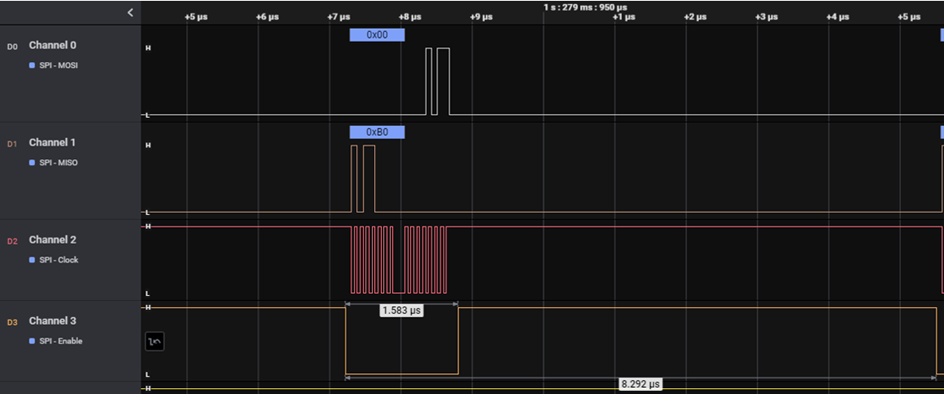
Pic 1.
The measured transaction time for one of the 16 channels was, respectively:
For a 16-channel transfer including the configuration word, 9.9 us * (16 + 1) = 168.3 us. With an acquisition interval of 200 us, we only had 31.7 us left for calculations. Unfortunately, the complex data processing and analysis algorithm, despite optimization, did not fit in the time left after transmission. Data transfer needed to be optimized.
Increasing the SPI interface clock frequency was not an option due to the hardware limitations of the A/D converter. Therefore, the only point for optimization was SPI access time, which takes much longer than data acquisition itself. The SPI hardware interface, however, made reducing this time impossible. In light of this, we decided to come up with a different solution to the problem.
A somewhat dated software implementation method for SPI interfaces, which is not popular among programmers, came to the rescue. This got rid of extended access time at the expense of reducing the data keying clock, which turned out to be an advantage in the end. We significantly reduced the radiated emissions from the CLOCK line, making it easier to pass several EMC tests later. We used proper thread synchronization and considerate task sharing between the two microcontroller cores to ensure data coherence.
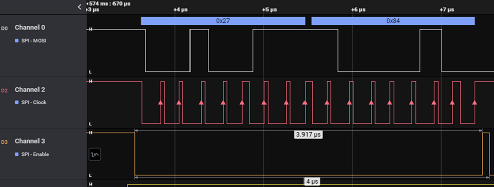
Pic 2.
The measured transaction time for one of the 16 channels was, respectively:
For a 16-channel transfer including the configuration word, 4.083 us * (16 + 1) = 69.4 us. We reduced the data acquisition time by about 100 us, which gave us 130.6 us for computation. This enabled us to seamlessly implement all functionalities with plenty of room for algorithm development.
Some methods, commonly considered unprofessional or outdated, may be the only solution in certain cases. Also, it is essential to ensure that a proper software development process allows for creative, non-standard solutions to problems that may arise.